128bpt Wiring Diagram
Diagram Toyota Vista Wiring Full Version Hd Quality Investinlazio It. A diverse line of Resideo initiating devices notification appliances communication devices keypads RF.
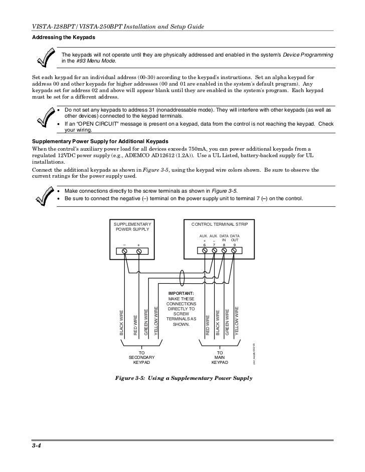
Install Guide Honeywell Vista 128bpt And 250bpt
Rrs Mod 2 Wire Smokes.

128bpt wiring diagram. The RS232 cable connects to a screw type connector on the top right corner of the main board. Wiring Connections for Zones 1-93-6 Figure 3-10. Refer to the N6361 Installation Instructions for wire routing instructions.
Increase the reliability and functionality of your home security system by installing the Honeywell iGSMV4G. If more than one keypad is wired to one run then the maximum lengths must be divided by the number of keypads on the run. SETUP OF CRESTRON HARDWARE.
All references in this manual for number of zones number of user codes number of access cards and the event log capacity use the VISTA-250FBPTs features. Step 1 2 3 4 5 Action Enter Output Programming in the 93 Menu Mode. VISTA-128BPTVISTA-250BPT Installation and Setup Guide 1-2 Features Hardwire and Optional Expansion Zones Provides nine hardwire zones.
When programming these zones in the Vista-128BPT choose a 24 Hour zone type such as 24 Hour Audible ZT 07 24 Hour Silent ZT 06 or 24 Hour Auxiliary ZT 08. Uses same wiring connection as Honeywell 5800 series receivers. 32F to 122F 0C.
WAVIS128BP -201 REV 101. Remote Keypad Sounder Wiring 44 Figure 3-23. Vista -128BPT Vista -250BPT Vista -128BPTSIA.
69 VISTA-250BP Summary of Connections Diagram. VISTA-128BP Summary of Connections Diagram. In the Normally Open circuit the 2K End of Line Resistor connects across the two terminals at the last panic switch wired in the circuit.
Remote Keyswitch Wiring 44 Figure 3-22. Wiring the VistaKey 48 Figure 3-25. Vista 128bpt And 4202 Relay Wiring Diagram.
Use 22 gauge twisted pair wire for polling loop connections. Ademco Vista 128fb 128fbp Wiring. Its components are shown by the pictorial to be easily identifiable.
1 Install and program the Honeywell Vista-128BPT secur it y sy stem according to Honeywell instructions. Wiring RadioRA 2 Interf acing wi th Honeywell Vista -128BPT Securi ty Systems Page 4 Programming Ov erv ie w Programming a RadioRA 2 system to interface with a Honeywell Vista-128BPT security panel is done in four phase s. Wiring Communicator to Keypad Terminals 46 Figure 3-24.
View and Download Honeywell VISTABPT installation and setup manual online. 70 VISTA-128SIA Summary of Connections Diagram. Product Speci cations Dimensions.
Supports up to 16 2-wire smoke detectors on zone 1. The Honeywell VISTABPT is an alarm control panel powerful enough for any commercial application. This is called Parallel wiring.
Comm11ct Security Communications Intrusion Alarm Commercial Solutions Guide Catalog Honeywell Secur. 2-Wire Smoke Detector on Zone 13-8. This fire and burglary control panel supports up to eight partitions and up to 128 zonespoints using hardwired wireless and V-Plex addressable technologies.
Item Feature Range Shipping Default SIA Requirement. VISTA-128BPTVISTA-250BPT for Stand-Alone access control perform the following steps. If the Tuxedo Touch is used as the primary system keypad maximum wire run length is 150 feet.
WIRING CE For CE installations ADEMCO N6361 EMI suppression bead is required. C2I-COM C2- COM2 C2 -COM3. Wiring 4 Connect the Tuxedo Touch in parallel with keypads and other peripheral devices using the keypad data ECP bus.
Honeywell VISTA-128BPT Installation And Setup Manual. 72 oz 204g Power requirement. Is the least efficient diagram among the electrical wiring diagram.
The new VISTA-128FBPT provides the ultimate protection for life and property. 638 x 360 x 110 1620 mm x 914 mm x 279 mm Weight. 6160 TUXS TUXW 6280S or 6280W and a UL Listed Bell.
Connecting the Backup Batteries 56 VISTA-128FBPT VISTA-250FBPT Summary of Connections Diagram Inside Back Cover. All references to the VISTA-128BP also pertain to the VISTA-128SIA. Vista 128 Installation Manual Pdf.
For type 1 program the ECP address and relay number. The VISTABPT is a member of the Honeywell VISTA Turbo Series of alarm control panels55 1. Ademco Vista 128bp Wiring Diagrams It is far more helpful as a reference guide if anyone wants to know about the homes electrical system.
Program the output type as 1 or 2. The differences between the two panels are outlined in the supplement accompanying the VISTA-128SIA. Automatically resets 4-wire smoke detectors using the J7 output when a code off is entered.
V Plex Devices Wiring Page 1 Line 17qq Com. Polling loop and protection loop wires can be brought in either through the back or front of the unit by removing the knockouts. 12 VDC at 125 mA Operating temperature.
VISTA-128BPT128BPT-SIA250BPT INSTALLATION AND SETUP GUIDE 1-2 SIA CP-01 Quick Reference Chart The minimum required system for SIA CP-01 is a VISTA-128BPTSIA Control one of the following keypad models.

How Do I Connect A 4193sn To A Vista 128bpt 250bpt Or Vista 50 Alarm Grid

Honeywell Vista 128bpt Connections Summary
Ademco Vista 128fb 128fbp Wiring
Honeywell Vista 128bpt Installation And Setup Manual Pdf Download Manualslib

What S The Wire Length Limit On A Honeywell Vista S Polling Loop Alarm Grid

How Do I Setup A 6160rf On A Honeywell Vista Alarm System Alarm Grid

How Do I Add A Siren To A Honeywell Vista System Using A 4204 Relay Module Alarm Grid

How Do I Add A 4193sn To My Vista 128bpt 250bpt Or Vista 50 Alarm Grid

Car Voltmeter Wiring Diagram In 2021 Wiring Diagram Car Alarm Home Alarm System
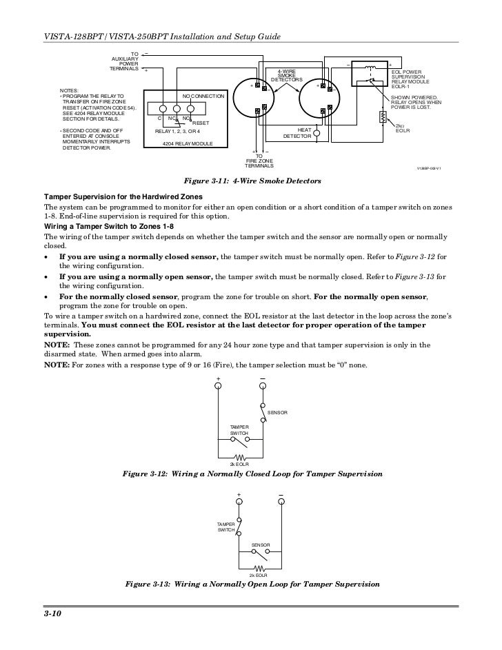
Install Guide Honeywell Vista 128bpt And 250bpt
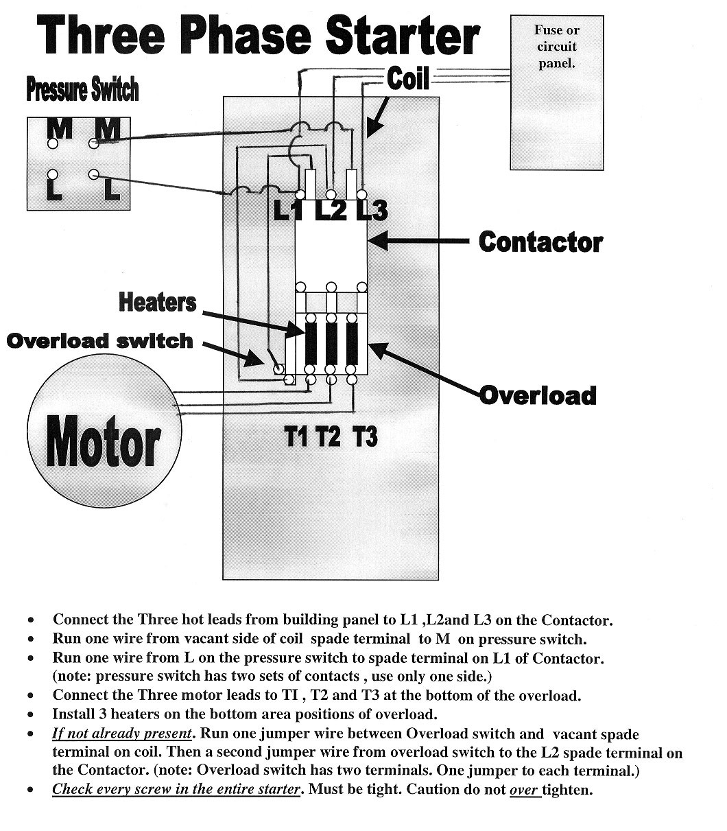
Weg Motor Wiring Diagram Single Phase Palotakentang

Diagram Garmin 128 Wiring Diagram Full Version Hd Quality Wiring Diagram Dmdiagram Amicideidisabilionlus It

Honeywell Vista 128bpt Connections Summary

Honda C70 Wiring Diagram Images Honda C70 Honda Shadow Honda
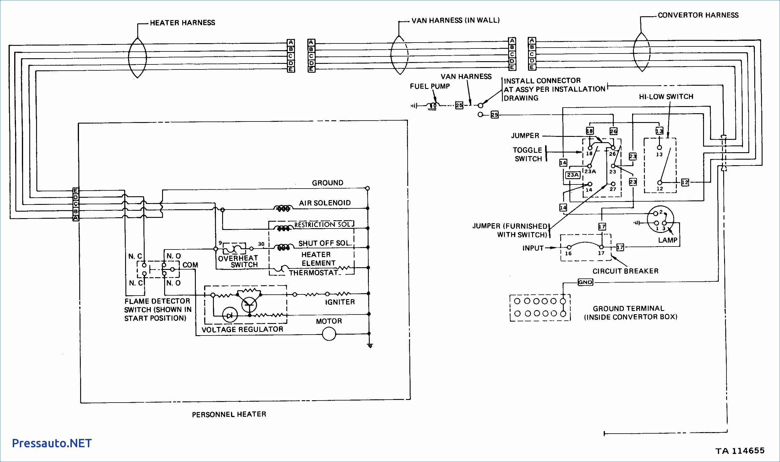
Diagram Toyota Vista Wiring Diagram Full Version Hd Quality Wiring Diagram Rediagram Amicideidisabilionlus It

