Dial Switch Wiring Diagram
Dial 6-Position Evaporative Cooler Wall Switch-71105 The Home Depot Swamp Cooler Switch Wiring Diagram. The dimmer switch will have stranded wires that must be sliced to the solid cable wiring in a pigtail fashion.
Rain Dial Rain Sensor Wiring Information This page is in response to a questions Joseph had about compatibility of the Rain Dial RD600 series timers and several Rain Sensors.

Dial switch wiring diagram. Assortment of intermatic timer t104 wiring diagram. You can find See diagram on page 9 5. It all rides on circuit that is being assembled.
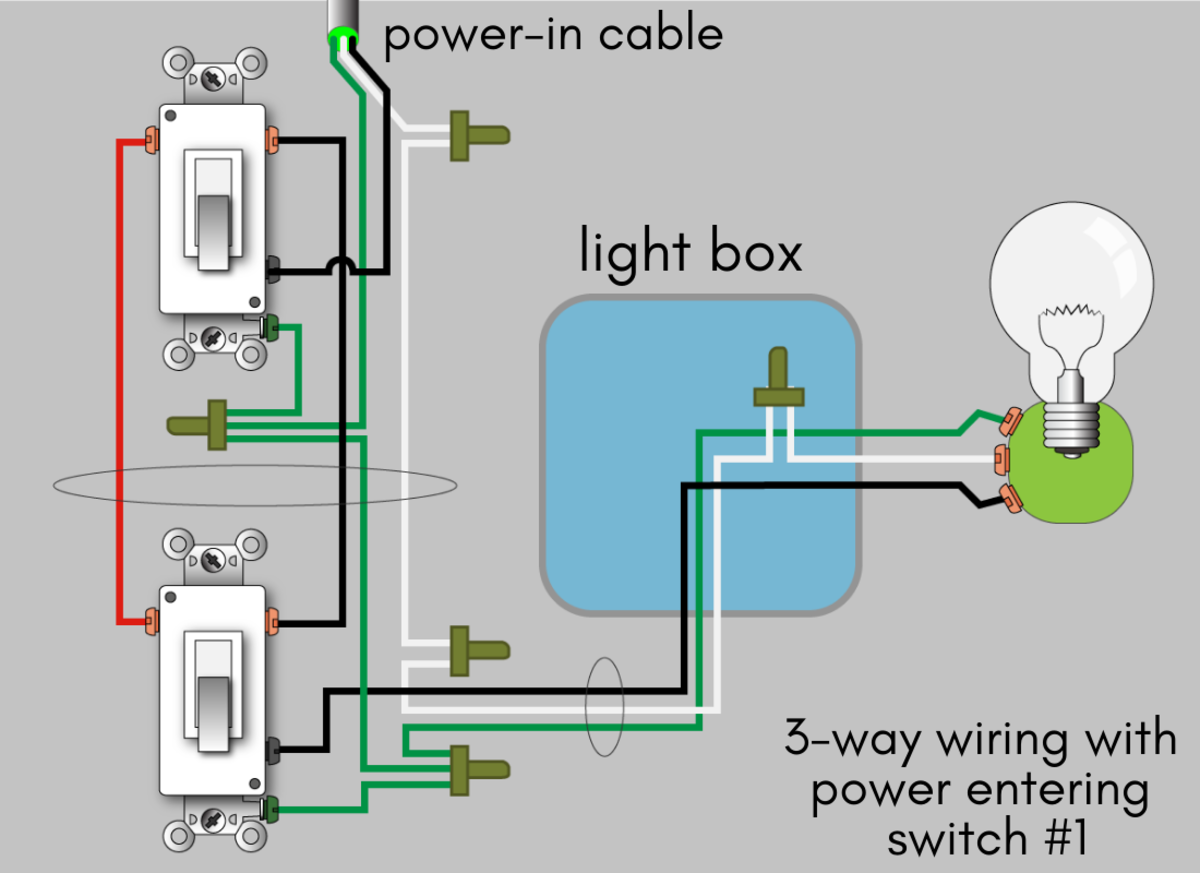
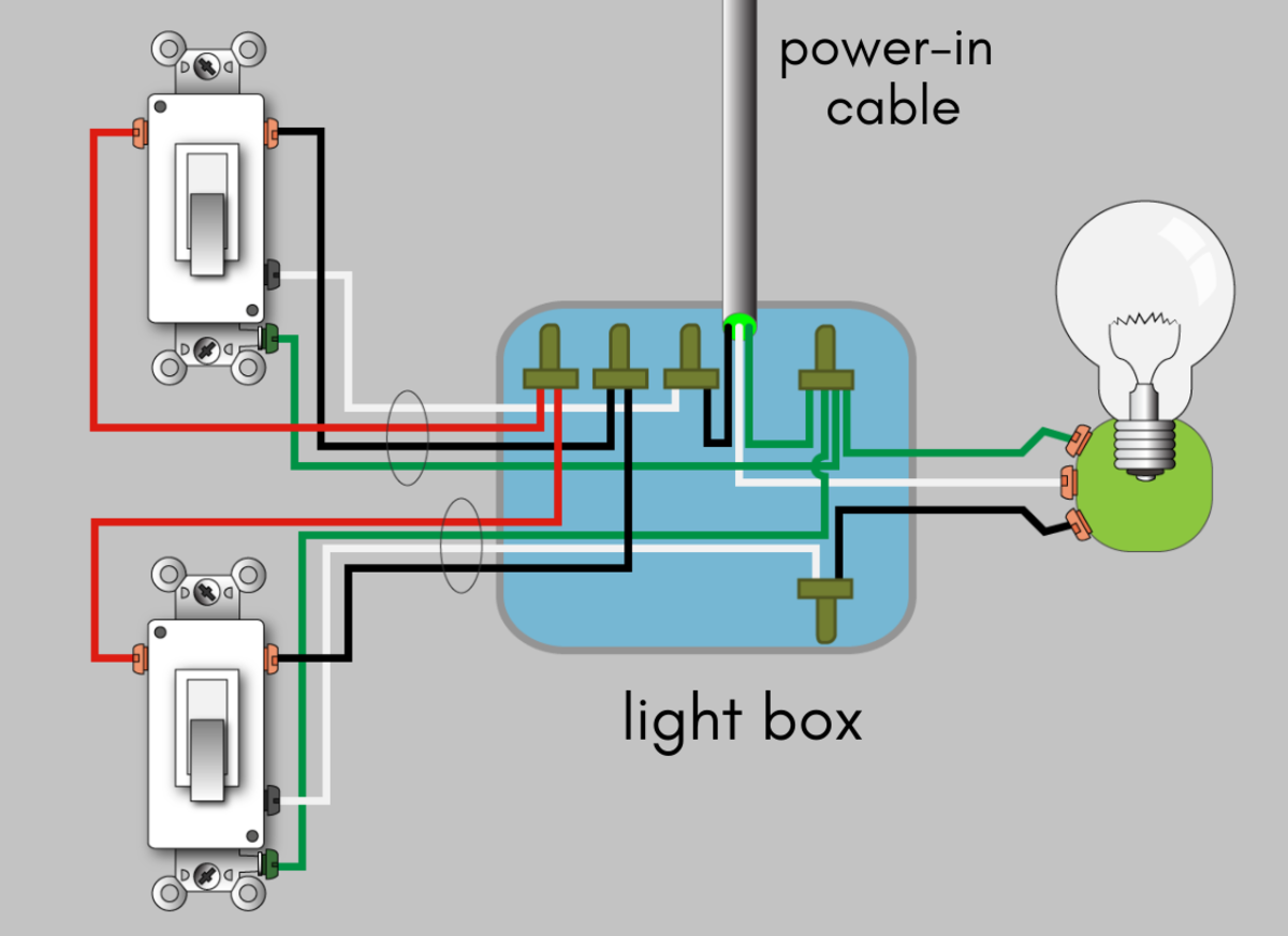
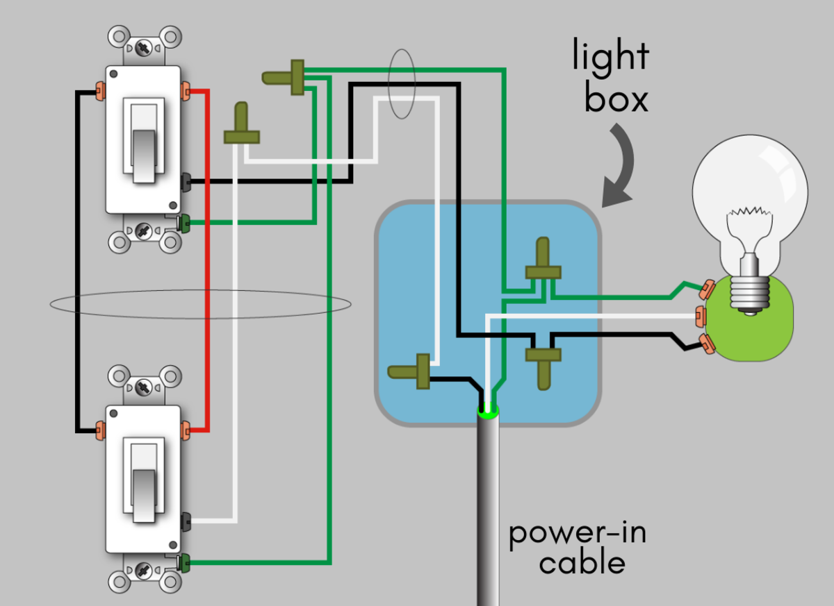
When wiring a 3-way switch circuit all we want to do is to control the black wire hot wire to turn on and off the load from 2 different locations. Make sure this fits by entering your model number this robertshaw controls universal infinite switch kit works diagram inverter transfer switch wiring diagram john deere wiring diagram john deere fuse box diagram. To order replacement indicate part no.
Baca Juga
- 09 Crf 450 Wiring Diagram
- 12 Volt Computer Fan Wiring Diagram
- 05 Honda Civic Radio Wiring Diagram
- 12v Wiring Diagram Software
- Kohler 200 Amp Transfer Switch Wiring Diagram
- 1719r Switch Wiring Diagram
- Push Switch Wiring Diagram
- 1970 Camaro Headlight Switch Wiring Diagram
- 12v Float Switch Wiring Diagram
- Double Gang Light Switch Wiring Diagram
Wiring diagram 240 v 2 wire and ground clock motor. At some point in an electronics project you. Wire a potentiometer as a variable resistor.
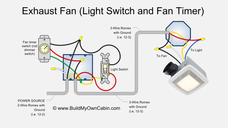
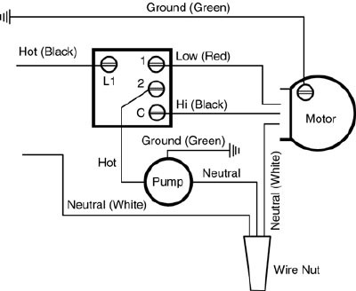
See evaporative cooler installation instructions and motor and pump instructions for proper motor and pump wiring. WIRING INSTRUCTIONSTo wire switch follow diagram above. The source power black wire is coming in from the left.
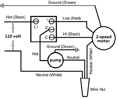
5 HP 28 FLA-240V AC. WIRING DIAGRAM 240 V 2 WIRE AND GROUND LR3730. Cooler motor connection with regulator 3 sd diagram cold air sample of cooling swamp wiring ceiling fan and isi 230v rs 390 piece capacitor how to wire an evaporative room pet world a c coil 80 series china dial 10 in amul 220 v 350 need help ao smith switch single winding 4 36 slot data instruction instructions 3sd 24 2 hp kit electric strategies oil systems for motors thermostat control.
Once all wiring is connected to the NEG -. The diagram here will give you a better understanding how this circuit works and how a 3-way switch is wired. 120 vac 60 hz.
See gauge selection table for normal service applica-tions. But it does not imply connection between the wires. To wire switch follow diagram above.
Use solid or stranded COPPER only wire with insulation to suit installation. Using the aid of the book you can easily do your own wiring. T104 24 HOUR DIAL TIME SWITCH Water Heater Timers.
1This KFI 2 lb winch is designed with a bolt pattern that is standard in this class of winch. Insert bare ends of wire under the pressure plateof terminals. The parts we will see inside the wiring diagram is like.
Dial 7109 2-Speed Rsk-2 Wall Switch. Dial Manufacturing 1 Hp Mastercool 2 Speed 6 Position Wall Switch. On the origional supplied with your panel the functions of the custom panel key switch will be written in for you.
24 hour dial time switch 1 page switch intermatic t103 supplementary manual. UL Recognized Component Rotary Switches. How a 3-Way Switch Works.
WIRING INSTRUCTIONSTo wire switch follow diagram aboveUse solid or stranded COPPER only wire with insulation to suitinstallation. As stated earlier the traces at a Swamp Cooler Switch Wiring Diagram signifies wires. Evaporative Swamp Cooler Switch Thermostat Wiring Hvac How To.
RESISTIVE INDUCTIVE TUNGSTEN OR 1000 VA PILOT DUTY EACH POLE 120208240 VOLT AC. This is the full diagram your panel may not be fitted with all these functions. INFINITE SWITCH WIRING DIAGRAM Page 1.
Switch is recommended for 120 volt applications only. These wiring diagrams are here for Dragon Marine Systems customers and are copyright of the company. Mastercool 1650 Sq Ft Downdraft Evaporative Cooler 5000 Cfm At.
Use 316 or larger screwdriver to tighten terminalscrews firmly. Clock motor voltage and cycle must be as specified. Includes Wall Switch Mounting Screws.
You are able to often depend on Wiring Diagram being an essential reference that can help you save time and money. 5f2a3 Epiphone Les Paul Black Beauty Wiring Diagram Wiring Resources. Many winch mounting kits are available that utilize this bolt pattern for the most popular ATVs and UTVs.
It ties into the common on the left switch see image below. At times the wires will cross. See gauge selection table for normal service applica-tionsTo make power connections remove 12 inch of insulationfrom wire ends.
This 6-position rotary wall switch is designed for 2-speed coolers with motors from 13 to 1 HP motors and it includes mounting screws and a wiring diagramPosition all wiring into junction box. Kits include dial adaptors to allow the customers dial to be used537. 24 HOUR DIAL TIME SWITCH DOUBLE POLE SINGLE THROW DPST 40 AMP.
The wiring diagrams in this link help explain how the rain sensors are wired into systems that are made for them or how you can add a rain sensor to a system that doesn. To wire as single pole normally closed move clock. Wg-- on motor cover.
Diagram Western Electric Telephone Wiring Full Version Hd Quality Jdiagram Lelzeviro It Classicrotaryphones Com Wiring Diagrams Diagram Lights Wiring For Old Wall Full Version Hd Quality Fxdiagram Am Ugci It. 2 HP 24 FLA-120V AC. Time pointer time dial off tripper manual lever on tripper typical wiring diagram clock motor 120240 volt 3 wire supply to loads ground line 2 line 1 a 2 4 gr.
This diagram is a basic schematic and is not intended to represent all methods of installation because of various cord plug and pump configurations. 11 way plug wiring diagram. Mount thermostat to junction box using the screws provided.
Fail Mastercool Mcp44 Window Evaporative Cooler Youtube. A wiring diagram is a streamlined traditional pictorial representation of an electric circuit. Use solid or stranded COPPER only wire with insulation to suit installation.
Injunction of two wires is generally indicated by black dot in the intersection of 2 lines.
File 3 Way Dimmer Switch Wiring Pdf Wikimedia Commons

Amp Hexadecimal Rotary Switch Robot Room

3 Way Switch Wiring Diagram House Electrical Wiring Diagram

How To Wire An Evaporative Swamp Cooler Switch Wiring Diagram
How To Wire A 3 Way Switch Wiring Diagram Dengarden
Guide To Wiring Switches Sockets Knowledge Base Jim Lawrence

Wiring Diagram 2 Humbuckers 3 Way Switch

Unique Light Switch Connection Diagram Diagram Wiringdiagram Diagramming Diagramm Visu Light Switch Wiring 4 Way Switch Wiring Diagram 3 Way Switch Wiring

Fourwayswitchdiagram2 Light Switch Wiring Electrical Switch Wiring Three Way Switch

Selector Switches Diagram Video And Selector Switch Product Oveview
Wiring Diagram Prs Guitar Wiring Diagram Guitar Tech

Pin On Dekal

How To Wire A 3 Way Switch Wiring Diagram Dengarden
How To Wire A 3 Way Switch Wiring Diagram Dengarden
Telecaster Wiring Diagram 3 Way Switch Humbucker

Hsh Wiring Diagram 3 Way Switch

Swamp Cooler Wiring Swamp Cooler Evaporative Cooler Hvac
2 Humbuckers With 5 Way Rotary Switch Wiring Diagram Fender Jazz Bass Wiring Diagram Luthier Guitar

Pin On Electrics Electronics